|
INSTALLATION AND OPERATING INSTRUCTIONS
IMPORTANT:
The vent control is NOT suitable for use at temperatures
exceeding 60C (140F).
The window or lid must never be LOCKED while the vent control is
installed.
Once the cylinder (= the rib tube) in the control has been removed,
then the window may be locked.
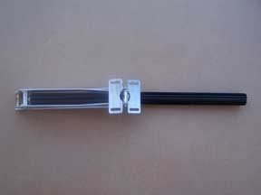
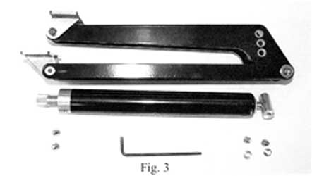
COMPONENTS: (see fig. 1)
1. Cylinder
(= rib tube). Installation : see below
.2. Piston rod
(= silverfish solid rod sticking out of the cylinder).
3. Spring and shock absorber
May be turned all around / facing the other way !!
4. Fitting brackets
May also be turned around / facing the other way
5. Shaped arms
(v-form, each with 3 locks, see below at pos. 8)
6. Straight arms
7. Relief bolt
for installation assistance (but to be removed
before fitting the cylinder in the same spot)
8. Locks
named A B C for deciding the opening height
YOUR OPTIONS:
Positioning your cylinder
I at the wall / outside the vent-opening: see fig. 2+5
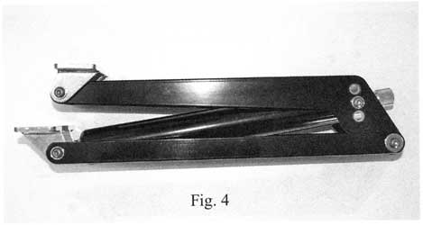
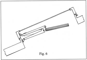
II inside the ventilation opening: see fig. 4+6
Opening height / lifting power
pos. A = 48 cm lifting I S kg see fig. 1 pos.
B = 40 em lifting 22 kg see fig. I pos.
C = 30 cm lifting 30 kg see fig. 1
The window MUST be able to move freely up to the chosen height. If
not, both the window and the opener may get damaged.
Weight of the window
Usually the vent control carry half the weight of the window,
while the other half rest onto the hinges. Meaning that if a window
weighs up to 30 kg, it may be open end up 48 cm (use lock A), and a
window weighing up to 44 kg may be open end up to 40 cm (use lock
B), or if a window weighs up to 60 kg it may be open end up to 30 cm
(using lock C).
Fitting brackets / options
Can be turned in the most favorable direction with regard to
fitting it onto the frame + sill.
Adjusting start-opening
Twist the cylinder (= rib-tube) on until 1 cm (1/2") of its own
thread is still visible. If the start-opening temperature is not as
desired, you may twist it a bit further. One turn = 0,5C/1F, and
turning clockwise = earlier opening start, while anti-clockwise =
later opening start. Adjustable anywhere between 17 og 25C.
VARYING OPENING HEIGHTS
Having more than one vent control in the same house/ room ? Please
notice, that the temperature may vary significantly within even
short distances - f.i. between floor and ceiling, between sun and
shadow, between close at a window and in the centre of the room.
MAINTENANCE
Grease ALL moveable connections + the piston rod at least once a
year using acid free oil or teflon spray.
INSTALLATION :
1. Firstly you will have to choose in which direction you want the
spring/shock absorber - and later the cylinder- to face (see fig.
5+6). If it does not by delivery face in the desired direction, then
you yourself can undo it and turn it a 180 (see fig. 2 + 3 + 4)
before refastening it.
2. When reassembling you will have to choose which of the 3 locks
(A-B-C) to use for fastening the arms (= deciding your opening
height).
3. Now it is time to hold the control up against the place where you
want it to be installed.
4. Turn the relief bolt (relieves the spring load during .4
installation) until the arms all by themselves stay in the desired
position for being fastened. Now the brackets can be fastened to the
frame and the sill (see fig. 5 + 6), while the window or the lid is
kept closed. Notice : the arms closest to the window should be
parallel to it (see fig 5 + 6).
5. Now it is time to install the cylinder (rib tube), but this
cannot be done until the relief bolt has been removed. If the
cylinder is warm already (or has .5 been warm), then the piston rod
has started moving outwards. You then need to open the window/lid by
hand, just enough for the cylinder thread to catch the thread inside
the spring/shock absorber! |


![]()
![]()
![]()
![]()
![]()

